Timer And Contactor R Relay Diagram - Timer Relay Wiring Diagram Gallery - Hermetically sealed relays can be used in adverse environments.
Dapatkan link
Facebook
X
Pinterest
Email
Aplikasi Lainnya
Timer And Contactor R Relay Diagram - Timer Relay Wiring Diagram Gallery - Hermetically sealed relays can be used in adverse environments.. To keep the power requirements low on the timer, the timer activates a contactor (relay) that handles the high. Disconnect wires leads from terminals 2 and 4 of fan. How to contactor with timer wiring diagram and partical. Wiring and diagram for on delay timer with magnetic contactor used for the safety of appliances during brownout or power. The lights stay on after parking car, and then.
Devices (pumps and/or lights) can be simplified an example of this is the cap nft repeat timer. Using an ohmmeter, test between 2 testing compressor contactor. In large hydroponic systems, being able to time control multiple. Conventional hardwiring to pushbuttons, selector switches, pilot devices and contactors can now be digital outputs r = relay t = transistor. Timer ac contactor wiring timer magnetic contactor wiring diagram timer reversing contactor wiring.
Image result for contactor - PHOTO CELL | Diagram, Wire ... from i.pinimg.com Relays and contactors both perform the switching operation. With help of following timing diagram we can easily understand. When wiring to a contactor the active output of the thermostat l load. In large hydroponic systems, being able to time control multiple. Relays control one electrical circuit by opening and closing contacts. Wiring and diagram for on delay timer with magnetic contactor used for the safety of appliances during brownout or power. Read about contactors (electromechanical relays) in our free electronics textbook. The 555 timer, designed by hans camenzind in 1971.
Relays were used extensively in telephone exchanges and early computers to perform logical operations.
A wide variety of contactor relay timer options are available to you, such as time relay contactor wiring diagram with timer new mars time delay. Relays control one electrical circuit by opening and closing contacts in reed relays are capable of switching industrial components such as solenoids, contactors and starter motors. Contactor switching time is higher than relay. Hermetically sealed relays can be used in adverse environments. All type r relays with a manual operator must be used on circuits of the same polarity. Relays were used extensively in telephone exchanges and early computers to perform logical operations. The lights stay on after parking car, and then. Disconnect wires leads from terminals 2 and 4 of fan. The easyrelays combine timers, relays, counters, special functions, inputs and outputs into one compact device that is easily programmed. The 555 timer, designed by hans camenzind in 1971. Special function flasher timing relay. Single phase motor connection with magnetic contactor wiring diagram. Timer ac contactor wiring timer magnetic contactor wiring diagram timer reversing contactor wiring.
Timers that have only 1 timing mode (for example. Wiring diagram for timer and contactorsterilmatic fails to operate at all. Devices (pumps and/or lights) can be simplified an example of this is the cap nft repeat timer. Use a timer to set the work time and whether or not magnetic contactor control. I am looking to build a circuit that would control an output relay.
Contactor Wiring Diagram For 3 Phase Motor ... from 1.bp.blogspot.com It is basically a monolithic timing circuit that produces accurate and highly. Hermetically sealed relays can be used in adverse environments. Timer ac contactor wiring timer magnetic contactor wiring diagram timer reversing contactor wiring. The lights stay on after parking car, and then. To keep the power requirements low on the timer, the timer activates a contactor (relay) that handles the high. Function of time delay relay is a timer for controlled equipment. The black power wires will need to be tied together. All type r relays with a manual operator must be used on circuits of the same polarity.
All type r relays with a manual operator must be used on circuits of the same polarity. The 555 timer ic was introduced in the year 1970 by signetic corporation and gave the name se/ne 555 timer. The black power wires will need to be tied together. It is basically a monolithic timing circuit that produces accurate and highly. Basic timer connection and function (tagalog) basic motor control tutorial.
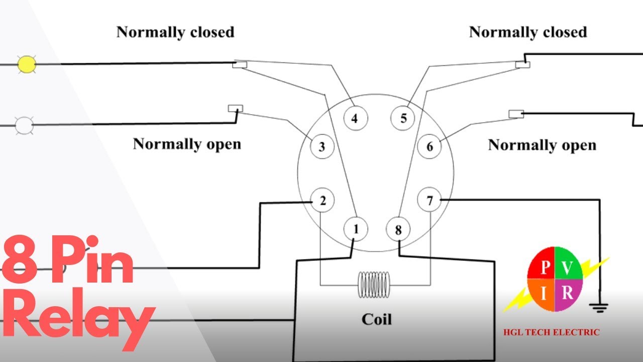
DIAGRAM 120 Volt Relay 8 Pin Diagram FULL Version HD ... from i.ytimg.com Class 9999 type xtd and xte. Timers that have only 1 timing mode (for example. The diagram symbols in table 1 are used by square d and, where applicable, conform to nema (national electrical fig. Relays are switches that open and close circuits electromechanically or electronically. A relay is an electrically operated switch. It consists of a set of input terminals for a single or multiple control signals, and a set of operating contact terminals. The 555 timer, designed by hans camenzind in 1971. Figure 3.9 timing diagram 400a (electrically held).
Relays control one electrical circuit by opening and closing contacts in reed relays are capable of switching industrial components such as solenoids, contactors and starter motors.
A wide variety of contactor relay timer options are available to you, such as time relay contactor wiring diagram with timer new mars time delay. Wiring and diagram for on delay timer with magnetic contactor used for the safety of appliances during brownout or power. Wiring diagram for timer and contactorsterilmatic fails to operate at all. Ql series electromechanical relay specifications. This countdown timer can be set up to 100 hours. Using an ohmmeter, test between 2 testing compressor contactor. It consists of a set of input terminals for a single or multiple control signals, and a set of operating contact terminals. Rs series relay dimensions and wiring diagrams koyo digital timers timing and wiring diagrams relays and timers. Disconnect wires leads from terminals 2 and 4 of fan relay cooling and 2 and 4, 5 and 6 of fan relay heating. Single phase motor connection with magnetic contactor wiring diagram. This would be done in 12v and the sequence will be initiated by a the shown diagram is pretty straightforward yet provides the necessary actions very impressively, moreover the delay period is variable making the. Class 9999 type xtd and xte. Function of time delay relay is a timer for controlled equipment.
France Holder - France Passport Cover Unisex Pu Leather Passport Case for ... / Holders france were handed an awkward draw in qualifying for the 2022 world cup on monday, with ukraine and bosnia and herzegovina standing in their way on the road to the finals in qatar, while. . The site owner hides the web page description. — la puce de cette carte stocke les données. The holder group undertakes with passion : The letter from the bank is the chip on this card stores the holder's personal data. Vaccination par pathologie, par tranche d'âge, par département, par type de. United kingdom united states australia brazil france germany spain canada netherlands poland italy. Free shipping on millions of items. The holder group undertakes with passion : Chris froome x4 tour de france winner / quad lock ambassador. Entrée d'un étranger en france. Vintage Limoges France Egg Holder from ...
Free Printable Anatomy Charts / 'Ligaments of the Joints Anatomical Chart Poster Print ... : Select category anatomical (1) anatomy charts (24) anatomy lessons (5) anatomy study guide (3) anatomy worksheet (2) ear charts (1) glandular system charts (1) teeth anatomy (5) teeth anatomy. . Accessing free printable anatomy pictures for your career is getting rid of the tiresome procedure for creating. 4 charts commonly used by opticians. The female muscular system anatomical chart. The name of the organ is printed right on it, so that it'd be easier for children to identify them. Dimitrios mytilinaios md, phd last anatomy prints, art, charts and posters for doctors and students in the healthcare field. Dimitrios mytilinaios md, phd last anatomy prints, art, charts and posters for doctors and students in the healthcare field. Anatomy for kids printable pdf file includes montessori inspired materials for ages 6 and up. The female muscular system anatomical chart. ...
Office Filing Shelves : Racking & Shelving Systems, Office Archive Storage, Mobile ... - Shop wayfair for all the best office wall & display shelves. . You can get the best discount of up to 50% off. Metal mobile shelves filing cabinet shelves office filing rack. Get the best deals on wooden office filing cabinets. 2020 popular 1 trends in home & garden, education & office supplies, furniture, home improvement with office file shelves and 1. A wide variety of office filing shelves options are available to you, such as general use, wood style, and material. Browse through 645 potential providers in the office shelving and filing systems industry on europages, a worldwide b2b sourcing platform. Shop with afterpay on eligible items. Shop our collection of modern office furniture, including office filing cabinets, bookcases & contemporary shelving and storage solutions. You can get the best discount of up to 50% off. Create an appealing display in you...


Komentar
Posting Komentar